
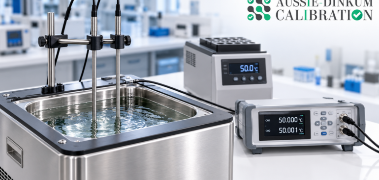
Temperature calibration services in Australia help businesses assess the performance of thermometers, temperature probes and measurement systems used in manufacturing, food processing, laboratories and equipment maintenance.
However, a reliable comparison requires more than placing a probe into a temperature source. The position of the sensing element, immersion depth and time allowed for stabilisation can all affect the result.
Understanding these factors helps businesses provide clearer calibration instructions and recognise why a probe may behave differently in the laboratory and during everyday use.
Why Do Probe Placement and Immersion Matter?
During comparison calibration, the probe being tested and a reference thermometer must experience sufficiently similar, stable temperatures.
A temperature bath or dry-block calibrator can have temperature differences across its working space. If the sensors occupy different thermal conditions, their readings may differ for reasons beyond the instrument’s measurement error.
Insufficient immersion can also allow heat transfer along the probe stem to influence the sensing element.
Common Setup Problems Include:
- Positioning probes outside the source’s characterised working zone.
• Using insufficient immersion depth.
• Aligning probe tips without considering sensing element locations.
• Selecting an unsuitable dry-block insert.
• Recording results before the probes stabilise.
• Allowing probes to move during measurement.
• Exceeding the permitted temperature of handles or cables.
• Assuming laboratory conditions represent every installation.
A documented setup helps the laboratory control these influences and explain the conditions under which results apply.
1. Identify the Probe and Its Sensing Element
Start by identifying the probe’s construction and intended use.
A resistance temperature detector, thermistor and thermocouple may have different sensing element sizes, positions and response characteristics. The visible end of the sheath does not always identify the centre of the active sensing region.
Manufacturer guidance highlights the importance of sensing element location when positioning a reference probe and a probe under test. Fluke
Useful Information to Provide:
- Probe manufacturer and model.
• Serial number and internal asset number.
• Sensor type.
• Sheath length and diameter.
• Sensing element location and length, where available.
• Permitted operating temperature.
• Minimum immersion requirements.
• Associated indicator, transmitter or data logger.
If the sensing element details are unavailable, tell the laboratory rather than assuming that the entire probe responds uniformly to temperature.
<h2>2. Understand What Causes Immersion Error</h2>
Immersion error occurs when insufficient insertion allows the environment outside the temperature source to influence the sensor.
One important mechanism is stem conduction: heat flows along the probe between the sensing region and the exposed stem, handle or surrounding environment.
In a hot source with cooler surroundings, this can pull the sensor temperature down. In a cold source with warmer surroundings, it can push the sensor temperature up. The effect depends on the probe and setup. Fluke
Factors That Can Affect Immersion Error:
- Probe diameter and construction.
• Length of the sensing element.
• Insertion depth.
• Difference between source and ambient temperatures.
• Thermal contact with the source.
• Exposed stem and mounting arrangement.
• Characteristics of the calibration medium.
A stable display alone does not establish that immersion error is negligible. A reading can settle while remaining influenced by heat transfer.
3. Select an Appropriate Immersion Depth
Follow the probe manufacturer’s requirements and the laboratory’s validated method.
There is no single immersion depth suitable for every temperature probe. Short probes, thick sheaths and specialised sensor assemblies may require different arrangements.
Some technical guidance uses diameter-based rules as an initial estimate. These should not replace equipment-specific instructions or an assessment of immersion effects.
Questions to Confirm:
- What minimum immersion does the manufacturer specify?
• Can the source accommodate the required depth?
• Is the full sensing region within the suitable working zone?
• Are handles and cable transitions protected?
• Does the available depth suit all requested temperatures?
• Is additional assessment needed for a short probe?
How Can Immersion Effects Be Investigated?
A laboratory may compare results at different insertion depths, allowing stabilisation after each change and accounting for the source’s temperature gradients.
Changes in the comparison can help reveal sensitivity to immersion. The investigation must distinguish stem effects from differences in source temperature at different positions.
Do not apply an arbitrary correction without a suitable technical basis.
4. Position the Reference and Test Probe Carefully
The reference thermometer and the probe being calibrated should occupy positions that support a valid comparison.
Where probes have different sensing element lengths, matching their external tips may leave their active regions at different heights.
Align the sensing regions as appropriate to the procedure and keep them within the source’s characterised working area.
Placement Checks Include:
- Identify the active region of each sensor.
• Position sensing regions at suitable relative heights.
• Keep probes appropriately close together.
• Maintain clearance required by the equipment instructions.
• Avoid unintended contact with bath walls or fixtures.
• Secure probes against movement.
• Record positions where they affect interpretation.
For liquid baths, manufacturer guidance recommends close grouping within the working area, sufficient immersion and stabilisation before comparison. media.fluke.com
5. Check Dry-Block Insert Fit and Working Zone
A dry-block calibrator transfers heat through an insert containing holes for the probes.
The insert must suit the probe dimensions and the calibrator’s operating requirements. An unsuitable fit can affect heat transfer and response.
Probe position also matters because temperature can vary along the insert and between holes.
Dry-Block Setup Checklist:
- Select an insert suitable for the probe diameter.
• Follow the specified fit and insertion instructions.
• Confirm sufficient depth is available.
• Position sensing regions within the characterised zone.
• Consider differences between reference and test holes.
• Confirm whether an external reference is required.
• Follow the permitted probe loading arrangement.
• Allow the assembly to stabilise after changes.
The controller display is not automatically the exact temperature experienced by every inserted sensor. Its suitability as the reference depends on the method and the source’s characterised performance.
What If the Probe Is Too Short?
Discuss the limitation before booking calibration.
The laboratory may need a different source, fixture or method. A short probe should not simply be placed into a standard setup if its sensing region cannot reach an appropriate zone with adequate immersion.
6. Control Placement in a Liquid Bath
A stirred liquid bath can accommodate different probe shapes, but suitable placement remains essential.
The bath medium must be compatible with the equipment and temperature range. Only parts designed for immersion should enter the liquid.
Liquid Bath Checks Include:
- Confirm a suitable bath medium.
• Maintain the required liquid level.
• Position probes within the characterised working space.
• Provide adequate immersion.
• Support probes securely.
• Avoid obstructing circulation.
• Keep non-immersible handles and connectors clear.
• Check conditions after adding or moving probes.
Adding several probes changes the bath’s thermal load and may increase stabilisation time. Follow the procedure’s loading limits and stability criteria.
7. Allow the Source and Probes to Stabilise
Reaching the selected temperature on the controller does not necessarily mean that every probe has reached equilibrium.
The source, reference thermometer and test probe can respond at different rates. Probe construction, loading and thermal contact affect the time required.
Before Recording Results:
- Confirm source stability against the procedure’s criteria.
• Observe the reference thermometer.
• Allow the test probe sufficient response time.
• Check for continuing drift.
• Reassess stability after repositioning probes.
• Use a defined reading sequence.
• Record relevant environmental conditions.
Avoid relying on one fixed waiting time for all probes and temperatures. Use evidence that the measurement arrangement has stabilised sufficiently.
8. Relate Calibration Conditions to Actual Use
Calibration establishes performance under documented conditions. Installation can introduce additional influences.
A probe calibrated with adequate immersion may produce different results when installed shallowly in a pipe, placed against a vessel wall or used in a poorly mixed product.
Application Details Worth Sharing:
- Normal operating temperatures.
• Available insertion depth.
• Use of a thermowell or protective pocket.
• Mounting position and orientation.
• Whether the measured medium is air, liquid or solid.
• Flow or mixing conditions.
• Required measurement tolerance.
• Whether the complete measurement system needs assessment.
Clarify whether the service covers the probe alone or the probe together with its indicator, transmitter or logger. Electrical simulation of an indicator does not assess the physical probe’s immersion behaviour.
A Practical Probe Placement and Immersion Checklist
| Calibration item | What to confirm |
| Probe identity | Model, serial number and sensor type |
| Probe construction | Sheath dimensions and sensing element details |
| Temperature range | Requested points suit the probe and source |
| Immersion depth | Depth follows instructions and the validated method |
| Sensor alignment | Active regions occupy suitable comparison positions |
| Working zone | Probes remain within the characterised source area |
| Dry-block insert | Fit, depth and loading suit the probes |
| Liquid bath | Medium, level and circulation are suitable |
| Stabilisation | Source and probes meet defined stability criteria |
| Measurement scope | Probe-only or complete-system calibration is clear |
| Application conditions | Installation differences are understood |
| Documentation | Relevant conditions and limitations are recorded |
What Should Happen When Probes Return From Calibration?
Inspect the equipment and review its certificate before returning it to service.
Check that the results relate to the correct probe and measurement system. Consider whether the calibration conditions support the intended application.
Recommended Actions:
- Confirm Identity: Match the probe and associated instrument to the certificate.
- Inspect Condition: Check the sheath, cable, connector and supplied accessories.
- Review Scope: Confirm the temperature points and components assessed.
- Check Conditions: Review reported immersion details and method limitations.
- Assess Results: Compare results and uncertainty with application requirements.
- Review Installation: Confirm that the intended placement provides suitable immersion and thermal contact.
- Authorise Release: Record any restrictions before returning equipment to use.
- Update Records: Save the certificate and update the equipment register.
If laboratory and workplace readings differ, investigate the installation and measurement conditions alongside the instrument’s calibration results.
Common Mistakes to Avoid
Small setup differences can make temperature comparisons difficult to interpret.
Examples Include:
- Assuming every probe senses temperature only at its tip.
• Applying one immersion depth to all probe designs.
• Matching sheath ends without considering active sensing regions.
• Using an unsuitable dry-block insert.
• Positioning probes outside the characterised working zone.
• Immersing handles or connectors beyond their ratings.
• Recording results as soon as the controller reaches its setpoint.
• Moving probes without allowing further stabilisation.
• Ignoring differences between calibration and installation conditions.
• Treating indicator-only testing as calibration of the complete probe system.
Provide installation details when requesting calibration so that relevant limitations can be discussed early.
Final Thoughts
Temperature calibration services in Australia depend on controlled probe placement, suitable immersion and sufficient stabilisation to produce meaningful comparisons.
Identifying the sensing region, selecting an appropriate source and documenting the setup help distinguish instrument performance from errors introduced by the measurement arrangement. Reviewing workplace installation conditions then helps businesses apply calibration results appropriately.