
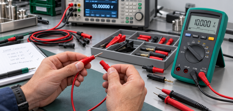
Multimeter calibration in Melbourne helps businesses assess the measurement performance of instruments used in electrical maintenance, manufacturing, equipment servicing and laboratory work.
However, reliable measurements depend on more than the multimeter itself. Test leads, probes, clips and other accessories form part of the connection between the instrument and the item being measured. Their condition and suitability can influence the readings obtained during everyday use.
Understanding how these components affect measurements helps businesses define their calibration requirements, investigate inconsistent readings and maintain suitable equipment for their applications.
Why Should Test Leads and Accessories Be Considered During Calibration?
Test leads connect the multimeter to the measurement point. Although they may appear to be simple accessories, their electrical characteristics and physical condition can affect the measurement system.
Fluke describes test leads as an integral part of the complete measurement system and explains that unsuitable connections can introduce errors, particularly when measuring small voltages or low resistance. media.fluke.com
A multimeter calibrated using laboratory leads may perform differently in practice when connected through damaged, contaminated or unsuitable workplace accessories.
Considering Accessories Helps Businesses:
- Identify possible sources of inconsistent readings.
- Understand the limitations of the calibration scope.
- Select accessories suitable for the measurement task.
- Account for lead resistance where relevant.
- Investigate intermittent connections.
- Identify accessories requiring separate assessment.
- Maintain clearer equipment records.
- Make informed decisions before returning equipment to use.
The aim is to understand both the instrument’s performance and the connections used during its intended application.
1. Understand What the Multimeter Calibration Covers
Before arranging calibration, confirm which functions, ranges and measurement points will be assessed.
A multimeter may offer DC voltage, AC voltage, current, resistance, capacitance, frequency and temperature functions. The agreed calibration scope may cover only selected functions.
The same principle applies to accessories. Sending leads or probes with the instrument does not automatically mean they will be assessed or included in the reported results.
Details to Confirm:
- Multimeter manufacturer and model.
- Serial number and asset identification.
- Required measurement functions.
- Operating ranges and calibration points.
- Accessories supplied with the instrument.
- Whether laboratory or customer leads will be used.
- Any accessory inspections or performance checks included.
- Reporting requirements and scope limitations.
Ask the provider to clarify any uncertainty before dispatching the equipment.
2. Consider Lead Resistance in Resistance Measurements
Test leads and their contacts contribute resistance to the measurement circuit.
In a two-wire resistance measurement, this additional resistance can become part of the displayed result. Its relative effect becomes more significant when measuring low resistance.
Simplified Example:
A technician measures a component with a resistance of approximately 1.00 Ω.
If the leads and connections contribute an additional 0.20 Ω, the displayed result could be approximately 1.20 Ω, before considering other measurement effects.
This example illustrates why a small lead contribution can matter when the resistance being measured is also small.
Points to Review:
- The resistance values normally measured.
- The accuracy required for the application.
- The condition and stability of the lead connections.
- Whether the instrument supports lead compensation.
- Whether a four-wire measurement method is available.
- The manufacturer’s instructions for the selected method.
Keysight explains that suitable four-wire resistance measurements help prevent lead resistance from being added directly to the measured value. www.keysight.com
3. Understand Two-Wire and Four-Wire Connections
The connection method affects how lead resistance influences a resistance measurement.
Two-Wire Resistance Measurement
A two-wire setup uses the same pair of leads to carry the test current and sense the voltage.
Lead and contact resistance can therefore contribute to the displayed result. Some instruments provide a relative or zero function to compensate for an initial contribution.
However, compensation depends on the measurement conditions remaining sufficiently stable. It does not resolve a loose connector or an intermittent lead.
Four-Wire Resistance Measurement
A four-wire setup uses separate current and voltage-sensing connections.
On a compatible instrument, this arrangement reduces the influence of lead and contact resistance. Fluke’s calibration guidance identifies four-terminal techniques as a way to minimise these effects. www.fluke.com.cn
Questions to Ask:
- Does the multimeter support four-wire resistance measurements?
- Is this method required for the intended application?
- Are the correct leads and terminals available?
- Will calibration cover the relevant resistance function?
- Does the workplace procedure describe the connection method?
Adding extra leads to a multimeter does not create four-wire capability unless the instrument supports that measurement arrangement.
4. Inspect the Physical Condition of Test Leads
Calibration results do not replace the need to inspect leads and accessories before use.
A lead may have visible damage, a loose plug or an unreliable internal connection even when the multimeter itself operates normally.
Inspect for:
- Cuts, cracks or deterioration in insulation.
- Exposed conductors.
- Damaged probe bodies.
- Loose or damaged plugs.
- Worn or contaminated probe tips.
- Damaged strain reliefs.
- Clips that do not hold securely.
- Signs of overheating or excessive wear.
- Intermittent operation reported by users.
Remove damaged accessories from service and follow the manufacturer’s instructions and workplace procedures for assessment or replacement.
Do not assume that an acceptable multimeter calibration result establishes the condition of every lead used with it.
5. Check Probe Tips, Clips and Adaptors
Different accessories provide different ways of connecting to a measurement point.
A probe tip may be suitable for a brief measurement, while a clip may be more appropriate when a stable connection needs to be maintained. Adaptors can provide access to particular connectors but also introduce additional connection points.
Review the Following:
- Compatibility with the instrument.
- Suitability for the measurement point.
- Secure mechanical connection.
- Condition of contact surfaces.
- Relevant manufacturer specifications.
- Any influence on the measurement arrangement.
- Whether the accessory is included in the calibration scope.
Accessories should be selected for the actual task rather than simply because they fit the multimeter terminals.
6. Consider Accessories With Their Own Measurement Characteristics
Some accessories do more than provide a connection. They convert a physical quantity into a signal that the multimeter displays.
Examples include current clamps, temperature probes and high-voltage probes.
Their performance may need to be assessed separately or together with the multimeter, depending on the application and agreed calibration method.
Current Clamps
A compatible current clamp may produce a voltage or current output corresponding to the current being measured.
Confirm the clamp model, output relationship, operating range and relevant multimeter settings. Calibration of the multimeter alone does not automatically establish the clamp’s performance.
Temperature Probes
For a multimeter used with a temperature probe, clarify whether the service assesses the temperature input, the probe or the combined system.
The reported results should be interpreted according to the configuration actually assessed.
Specialist Probes and Adaptors
Discuss specialist accessories with the provider before booking. Their suitability, specifications and calibration requirements may differ from standard test leads.
7. Pay Attention to Low-Voltage and High-Resistance Measurements
Some measurements are particularly sensitive to the connection arrangement.
For very small voltage measurements, connections involving dissimilar metals and temperature differences can introduce unwanted voltages.
For high-resistance measurements, leakage through leads and fixtures can influence the result. Keysight identifies leakage currents in these components as a source of high-resistance measurement error. www.keysight.com
Information to Discuss With the Provider:
- The smallest voltages measured.
- The highest resistance ranges used.
- Required measurement accuracy.
- Lead and connector types.
- Relevant environmental conditions.
- Cleaning and handling requirements.
- Any specialist connection methods.
- Observed instability during normal use.
The connection arrangement should suit the measurement requirements and the instrument manufacturer’s guidance.
8. Identify Accessories in Equipment Records
Where an accessory forms part of a controlled measurement setup, it should be identifiable in the organisation’s records.
This is particularly useful when multiple similar probes, clamps or lead sets are used across several instruments.
Information to Record:
- Accessory description.
- Manufacturer and model.
- Serial number, where available.
- Internal identification number.
- Associated multimeter.
- Intended application.
- Inspection or calibration status.
- Replacement date, where relevant.
- Restrictions or special instructions.
Clear identification helps staff determine whether the accessory in use matches the one assessed or specified in the workplace procedure.
A Practical Test Lead and Accessory Review Checklist
| Review item | What to check |
| Instrument identity | Manufacturer, model, serial number and asset number |
| Calibration scope | Required functions, ranges and test points |
| Standard leads | Condition, compatibility and secure connections |
| Probe tips | Damage, wear and suitability for the measurement point |
| Clips and adaptors | Contact condition and mechanical security |
| Resistance method | Two-wire or four-wire arrangement, where supported |
| Lead compensation | Availability, correct use and connection stability |
| Current clamps | Identification, output relationship and assessment scope |
| Temperature probes | Whether the input, probe or combined setup was assessed |
| Specialist accessories | Applicable specifications and calibration requirements |
| Report details | Accessories and configurations identified where relevant |
| Equipment records | Inspection status, replacements and approved use |
Hypothetical Example: Investigating Inconsistent Resistance Readings
A Melbourne maintenance workshop uses a multimeter to check low-resistance components.
The instrument returns from calibration with acceptable results for the resistance points assessed. However, technicians continue to obtain inconsistent readings when using an older workplace lead set.
Example Review:
- Instrument identity: The multimeter matches the calibration certificate.
- Calibration scope: The relevant resistance function was assessed.
- Test configuration: The laboratory used its own suitable leads.
- Workplace accessories: The workshop’s older lead set was outside the agreed scope.
- Inspection: One connector shows signs of wear and does not connect securely.
- Further assessment: A competent person investigates the lead set.
- Corrective action: The unsuitable accessory is replaced.
- Verification: The workshop confirms satisfactory operation before resuming the task.
- Previous use: Earlier measurements are reviewed where the identified issue could have affected decisions.
This example is illustrative. The appropriate investigation depends on the instrument, measurement requirements and workplace procedures.
How to Prepare Equipment for Multimeter Calibration in Melbourne
Preparing clear information helps the provider understand the service required.
Suggested Preparation Steps:
- Identify the Instrument: Record the manufacturer, model, serial number and asset number.
- Describe Its Use: Explain the measurements performed and the ranges that matter.
- List Relevant Accessories: Identify leads, clamps, probes and adaptors requiring attention.
- Explain Known Problems: Describe unstable readings, intermittent connections or recent damage.
- Agree on the Scope: Confirm which functions and accessories will be assessed.
- Confirm Reporting Requirements: Discuss results, uncertainty and any conformity statement required.
- Package Equipment Carefully: Follow the provider’s instructions for transport.
- Keep Dispatch Records: Record the items sent and retain the agreed service details.
If a particular accessory is essential to the task, discuss it explicitly rather than assuming it will be included.
Review the Calibration Report Before Returning Equipment to Use
After calibration, compare the report with the service requested and the equipment received.
Check the Following:
- Instrument identification.
- Required functions and ranges.
- Reported measurement results.
- Applicable acceptance criteria.
- Measurement uncertainty.
- Any conformity statement and decision rule.
- Accessories included in the assessment.
- Comments, limitations or exclusions.
- Adjustment or repair details, where applicable.
- Physical condition of the returned equipment.
An acceptable result for the multimeter does not automatically establish the performance of an accessory that was outside the scope.
Resolve missing or unclear information before approving the equipment for its intended application.
Common Mistakes to Avoid
Assuming All Supplied Accessories Were Calibrated
Confirm the agreed scope and check which items are identified in the report.
Ignoring Lead Resistance
Consider its contribution when making two-wire low-resistance measurements.
Using Compensation to Overlook an Unstable Connection
A relative or zero function cannot repair a damaged lead or secure a loose connector.
Treating Continuity as a Complete Lead Assessment
A continuity indication does not establish insulation condition or suitability for every application.
Replacing Accessories Without Reviewing Suitability
Check the replacement against the manufacturer’s requirements and the intended measurement task.
Failing to Record Accessory Changes
Update records when replacements affect an identified or controlled measurement setup.
Working With Aussie Dinkum Calibration in Melbourne
When arranging calibration with Aussie Dinkum Calibration, explain how the multimeter is used and which accessories form part of the everyday measurement setup.
Providing this information helps establish the required service scope and reporting arrangements.
Information to Discuss With the Calibration Provider:
- Multimeter manufacturer and model.
- Serial number and asset identification.
- Required functions and operating ranges.
- Important calibration points.
- Applicable accuracy requirements.
- Test leads and accessories to be assessed.
- Current clamps or temperature probes used.
- Intermittent or unexpected readings.
- Required certificate and accreditation details.
- How additional work or unexpected findings will be communicated.
Confirm the available service and accessory coverage before sending the equipment.
Final Thoughts
Multimeter calibration in Melbourne provides measurement information that helps businesses assess an instrument’s suitability for its intended use.
Test leads and accessories also deserve attention. Their resistance, contact condition, compatibility and measurement characteristics can influence the results obtained in the workplace.
Define the required calibration scope, identify relevant accessories and review the report before returning equipment to use. A consistent approach helps businesses maintain reliable measurement setups and clearer equipment records.